• You are currently viewing our boards as a guest which gives you limited access to view most discussions and access our other features. By joining our free community you will see less advertisements, have access to post topics, communicate privately with other members (PM), respond to polls, upload content and access many other special features. Registration is fast, simple and absolutely free so please, join our community today!

    If you have any problems with the registration process or your account login, please contact us.

Com port voltage

Buellxb Forum

Help Support Buellxb Forum:

Chicknstripn

Well-known member
Joined
Aug 17, 2014
Messages
2,144
Location
High Point, NC
Looking for a little electrical guidance regarding the voltage at the communication/diagnostics port. I've tried my Bluetooth module and I'm not getting any power. I think my wiring is faulty at the diagnostic plug. I'm getting .73 volts out of 2 of the 4 pins.
I've searched the 2007 and 2005 service manuals, I even looked through the 2008 electrical trouble shooting and haven't been able to find what I'm looking for.
I did stumble across an old thread that had some info. The thread stated that 3 of the 4 pins should have 1volt of power.
Can anyone shed some light on this for me? I'd like some more info before I start tearing into my wiring.

And since I know someone will ask; my bike is a 2007xb12r with 43k. It has a Buell race ECM, 1250kit, 540(I think, too many cob webs) cams, and headwork. I'm sure I'm leaving out some other irrelevant little mods I've done.... ...biggest thing is the bike has a 12s wire harness. Harness was swapped in order to accommodate a ridiculous single headlight mod.
Hey, it's my bike. I'll do what I want with it!

Because the wiring is essentially the same as an xb12s I posted in this section.

Thanks for the help
 
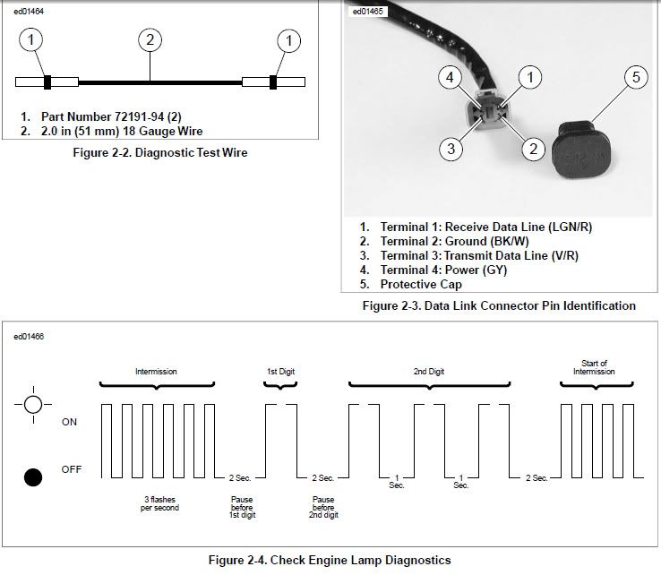
1 and 3 are 5 volt signals. 4 is 12volts, and 2 is ground.

CheckEngineLampDiagnostics.jpg
 
Thanks AZ! That's perfect!
I greatly appreciate the time you put into helping me out!
For future reference, and to save me from wasting anymore of your time; in what manual and in what section of said manual did you find that info?
 
I just googled "buell jumper cel" knowing it would bring up how to check the codes with a jumper wire. This is in the service manual though, not sure of which section though.
 
Fair enough.
I was google searching com port voltage test and diagnostic plug voltage with little success.
I guess my google skills are quite subpar.
Thanks
 
So, it's been a while since I started this post and I still haven't found the root of my problem. I took apart all the wiring in the tailsection and haven't found any obvious issues. I performed a continuity test between the diagnostic plug and its associated wires at the ECM plugs and the 12volt(gray) wire seems to have an issue at the ECM side. Or my continuity test might be flawed.
Anyway, I plan on taking the plugs for the ECM apart and thoroughly cleaning them.
Does anyone know if there are any other areas of the harness I should be checking?
 
Isn't the diagnostic plug included in the wiring diagram, that would tell you what pins to check for continuity.

Try buellmods.com for a service manual .pdf you noob.
:angel: hee hee
 
As I stated previously, continuity has been checked. I think I did it correctly. Will revisit my process to make sure.
Manual doesn't show where the wires go, physically, in between the components in question.
I've exposed all the wires in the tail section, I'm just wondering if I need to check the section of loom along the frame, that's inside the protective hard plastic cover.
I'll report back after I clean the connectors and hook everything up again.

Oh, and after I learn to read that dam manual! I was really hoping I wouldn't have to do that!
 
DDFI3 data link connector tx and rx wires are light green/red and violet and red. DDFI2 manual I have with me on my phone doesn't have the wire diagrams...
 
Just reread that and you're checking the power... The data link connector gets power from the auxiliary relay...
 
By auxiliary relay do you mean the flasher relay or are you referring to the relays in the fuse block?
I think I checked the auxiliary fuse but I'll definitely double check that. I'm pretty sure the all the relays on the bike work as they should. The diagnostic plug is the only electrical component not functioning properly.
 
Last edited:
Looking for a little electrical guidance regarding the voltage at the communication/diagnostics port. I've tried my Bluetooth module and I'm not getting any power. I think my wiring is faulty at the diagnostic plug.

You have to turn key switch ON and then turn ignition ON to be able to work with Buelltooth.

See Engine Management Circuit wiring diagram in the service manual to see the wires you need to check. The picture below is for 2009 Buell XB 12 Scg.

Wires.jpg
 
Last edited:
Are you saying I need to have the key on and the run/engine switch(most commonly referred to as the kill switch) on for the Bluetooth dongle to work?
I'm going to feel REALLY stupid if this is the one step I over looked before taking things apart.
ECMspy doesn't work the same way does it? I don't ever remember this being an issue with spy unless I was checking the timing.
Man, it's been so long since I used these diagnostic tools, I might be confusing myself.
From the diagram you posted, I think you're right.
I'm an idiot.
I assumed the ignition and keyswitch were synonymous.
I'm going to double check this tomorrow and report back.

Man, I really need to learn how to read wire diagrams!
 
Last edited:
Yes, For a Buelltooth to be powered key must be on, and kill switch in the run position .just a over sight.

Pair and Connect your Buelltooth Device to EcmDroid
Pairing your Buelltooth is as simple as any other bluetooth device. Once paired, you will not have to repeat this process unless an unpairing of the device is performed.

Download and install the EcmDroid Application on your Android device.
Plug the Buelltooth device directly into your diagnostic connection. Piggy-back devices such as Protune must not be connected.
Turn the key on and run switch to run. The LED on your Buelltooth will now be flashing. If you expect to have the bike on for an extended period of time it is suggested that you disable/disconnect the headlight or connect a battery charger. *If the battery of your motorcycle is allowed to drain to a level that is insufficient the unit will not work properly. If the battery can't start the bike, then it can't power the Buelltooth.
In the Settings/Bluetooth section of your device, perform a search for new devices. The Buelltooth will initially appear as a MAC address, or simply labeled as "Misc". Select this device.
 
Last edited:
Thanks for the cut and paste directions!
Like I said, I hope I didn't overlook this step.
I'll go through the process again tomorrow and report back.

Thanks for the insight guys.
I appreciate all the replies!
 
Put this useless thread to rest. I'm an absolute idiot.
Looks like my com port/diagnostic plug works just fine.
Sorry for wasting anyone's time.
And as always, thanks to everyone that provided feedback. I greatly appreciate it!
Looks like it's time to do some studying.
 
You are one of the MOST knowledgeable Buellers on the Board !!!!!

Dont feel bad , just the other day my truck wouldn't start, when I turned the key ?? It was already running. LOL
 
Last edited:
Back
Top