thrstrmech
Well-known member
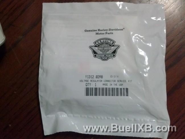
So, it began with the replacement of the 77 connector with the new updated one

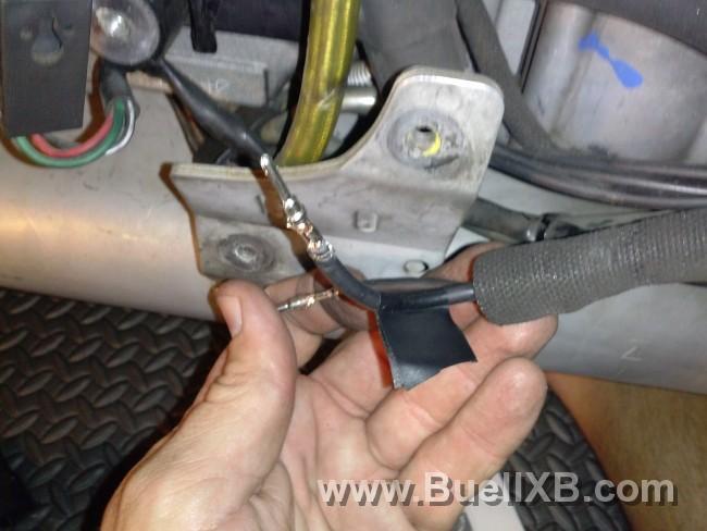
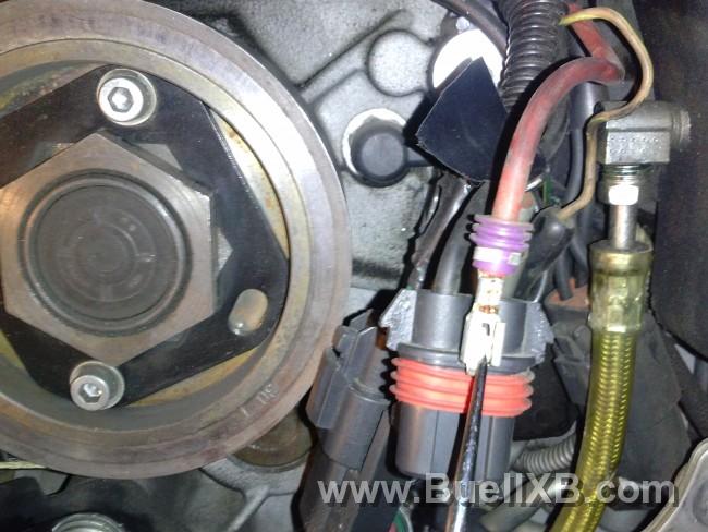
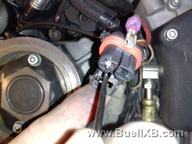
Disconnect the negative battery terminal before you begin the repair, next remove your chin fairing followed by the pulley cover. Use some low strength Loctite when you reinstall both of those items. Locate the 77 connector and mark your wires accordingly, first pic is the wire from the voltage regulator...you get the idea
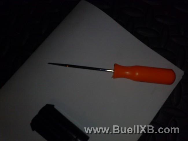
Next you'll need a scribe to remove the blade connectors from the connector halves
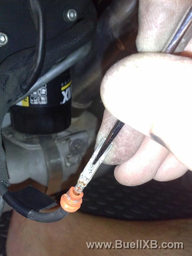
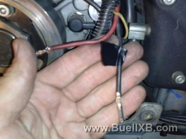
There's a tab on the blade connector both male and female ends, that you have to push down on to release it from the connector housing


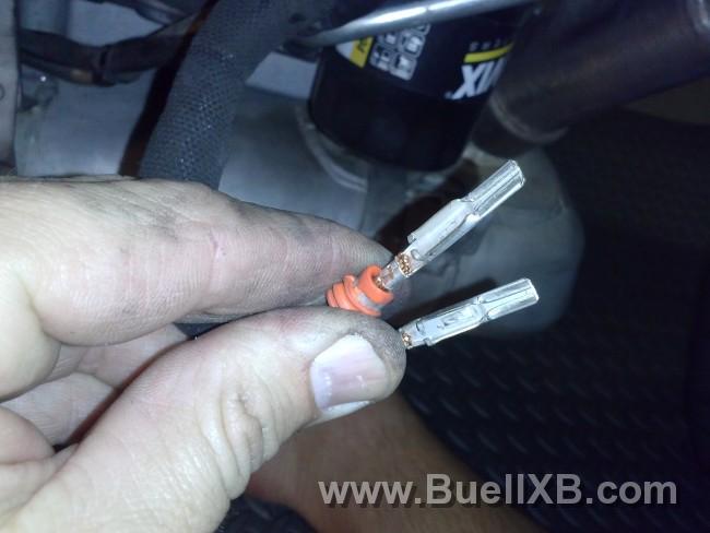
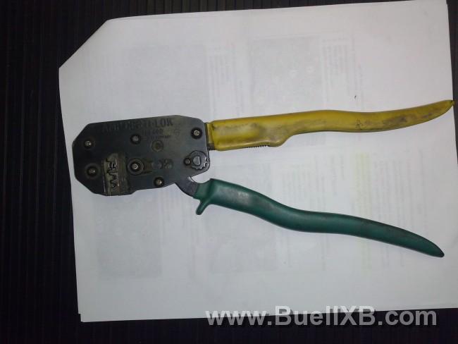
Cut the connectors off as close as possible and crimp new connectors on (pins and sockets) a tool like this is needed for proper crimping
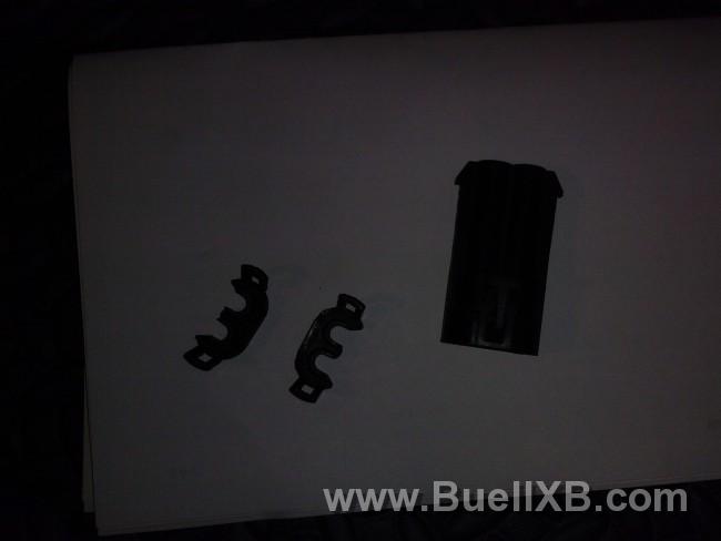
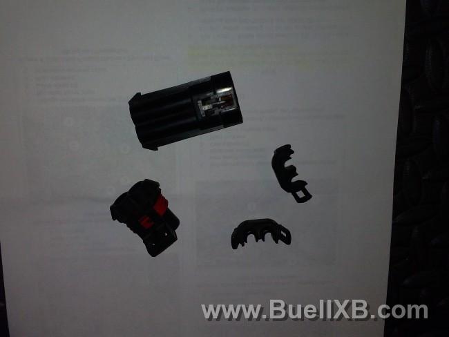
Insert connector pins and socket into corresponding halves and install the wedges (socket connectors go into the shorter connector housing along with the longer wedge / pin connectors into the larger connector housing with the shorter wedge).

Connect the halves and before you tidy up and reinstall the pulley cover and chin fairing, reconnect the battery and turn the bike over to make sure you did the job right
Some of the pics may not be in order, sorry...but didn't want to drag this out, so hopefully this will help you in replacing the 77 connector.
Disconnect the negative battery terminal before you begin the repair, next remove your chin fairing followed by the pulley cover. Use some low strength Loctite when you reinstall both of those items. Locate the 77 connector and mark your wires accordingly, first pic is the wire from the voltage regulator...you get the idea
Next you'll need a scribe to remove the blade connectors from the connector halves
There's a tab on the blade connector both male and female ends, that you have to push down on to release it from the connector housing
Cut the connectors off as close as possible and crimp new connectors on (pins and sockets) a tool like this is needed for proper crimping
Insert connector pins and socket into corresponding halves and install the wedges (socket connectors go into the shorter connector housing along with the longer wedge / pin connectors into the larger connector housing with the shorter wedge).
Connect the halves and before you tidy up and reinstall the pulley cover and chin fairing, reconnect the battery and turn the bike over to make sure you did the job right
Some of the pics may not be in order, sorry...but didn't want to drag this out, so hopefully this will help you in replacing the 77 connector.