• You are currently viewing our boards as a guest which gives you limited access to view most discussions and access our other features. By joining our free community you will see less advertisements, have access to post topics, communicate privately with other members (PM), respond to polls, upload content and access many other special features. Registration is fast, simple and absolutely free so please, join our community today!

    If you have any problems with the registration process or your account login, please contact us.

Any last ideas before I dive into the world of custom tunes?

Buellxb Forum

Help Support Buellxb Forum:

AFV was locked at 100% as well as closed loop disabled for all times datalogging with the WB mentioned above. The 105% is where AFV was at before disabling closed loop for initial datalog, just want to clarify the proper procedure.

What WB did you go with? Mine is an AEM UEGO I pulled from my supercharged car. If I had one that worked with ECM MONO I would have solely used that software instead. Gunter set it up to be streamlined and work flawless it appears without the need for secondary software.
 
Also not directed at anyone but just want to spread how AFV actually works. When you have closed loop enabled each fuel map has two sections closed and open loop. O2 data is constantly used in closed loop AND closed loop cells are adjusted on the fly to achieve 14.7 AFR (cell numbers don't change but the ECM makes these changes I real time). These real time changes effect AFV% which is what the ECM uses as a multiplier on the open loop cells. Example: you start out with AFV reset at 100% and ride for 30min, during this time the NB O2 reports leaner than 14.7 AFR. For a time and the ECM make note by adjusting AFV percentage up 103% ALONG with real-time fueling of the closed loop cells this lean condition happened. Now you are riding upper RPM WOT so the ECM applies 3% fuel to each open loop cell on top of its value it got from AFV sitting at 103%.

Also keep in mind you can't ask for more than 255 in a fuel cell even with a multiplier or enrichment table because 255 is the the same as 100% duty cycle on the injector.

Hope this makes sense to those learning. Keep in mind it is going to change day to day, it is supposed to do that.:up:

EDIT: Also want to add same goes for closed loop reading overly rich affecting AFV in negative percentage. Example: AFV at 97% would pull 3% fuel from open loop cells.
 
Last edited:
In TunerPro data in my tables looks like this and I'm thinking could be another thing that needs attention.

luVuJQD.jpg


which is very different from the tuning guide. Thats why I was wondering if you had a table you could post up, or maybe lowkey could chime in with his.

Yep those look exactly right for the race .bin, which was my starting point for tuning.
Scaled columns and rows.jpg

If you want to edit your rows and columns, use these axis tables under the tables tab. These are mine above, if you choose to do this make sure to take the cell data from the closest columns or rows on either side of your new one so you can populate with good data. Example: 1000RPM column and 2000RPM column with data and you want to input a 1500RPM column you would take the cell data on either side and split the difference 50% to populate the new 1500RPM column.

Judging by the date of this .bin I made this one a year ago so its been a while... haha
What else would you like me to look at while I'm booted into windows (which I hate using on a mac).
 
Here's a couple more screen grabs, this time how to setup a wideband properly in Megalog.

Custom Linear WB.jpg

Here is the calculated linear line I used the graph software linked earlier to make, this allows megalog to properly adjust the fuel maps by knowing the exact AFR for the 0-5 Voltage range. Even though the the AEM is linear AFR reading doesn't start moving on either end of the voltage spectrum until a couple points in (true of all WB's I'm sure) so along with the voltage point of movement for actual AFR movement and the supplied chart with your WB you can caluclate for your WB as I have done. I believe almost all do NOT do this and megalog is adjusting the maps incorrectly because of it. NOT TO BE OVERLOOKED IMO!

AEM adjusted values.jpg

For reference the gauge reads 8-18 AFR but you can see I had to extend the AFR on both ends so a linear line hit 0-5 volts.
 
Last edited:
lowkey,
If I understood you right, setting AFV to 100% locks ecu from making a change while data loging, tuning with WB. Also even thought there is only a certain spots on the map that closed loop is active and monitored by ecm to be able to make a change. When change is applied its to a global map and not just the closed loop are, is that right?

Good infor on the 255 being the max injector duty cycle. I had hard time getting information around that topic. Also do you know what a PW is measured in MegalogViewer? For example, when at idle, PW for cylinders one and two are around 3. What does that 3 represent?

I'm still not quite sure on how you came up with the numbers to populate AFR in MegalogViewer using the scale https://graph.soft112.com. How did you get 7.3125 for 0v and 19.1875 for 5 v? Did you get/use data sheet for your WB sensor?
I'm using Bosch LSU 4.9 and hardware/driver from 14point7.com to make it run. I haven't looked at the data sheet for that controller to see exactly where the dead band is. Again, great find, but I'm lost as to how you came up with those numbers.

Great point on making the fuel map more effective by getting rid of the 0 and 8000 rpm rows. I changed mine and plan on populating new rows using the method you described.


P.S. This is my second time typing this up. For some reason post from this morning got jacked up and deleted. If I remember what I had typed up this morning I'll post it up. Thanks for the input your information is very helpful.
 
Last edited:
lowkey,
If I understood you right, setting AFV to 100% locks ecu from making a change while data loging, tuning with WB. Also even thought there is only a certain spots on the map that closed loop is active and monitored by ecm to be able to make a change. When change is applied its to a global map and not just the closed loop are, is that right?
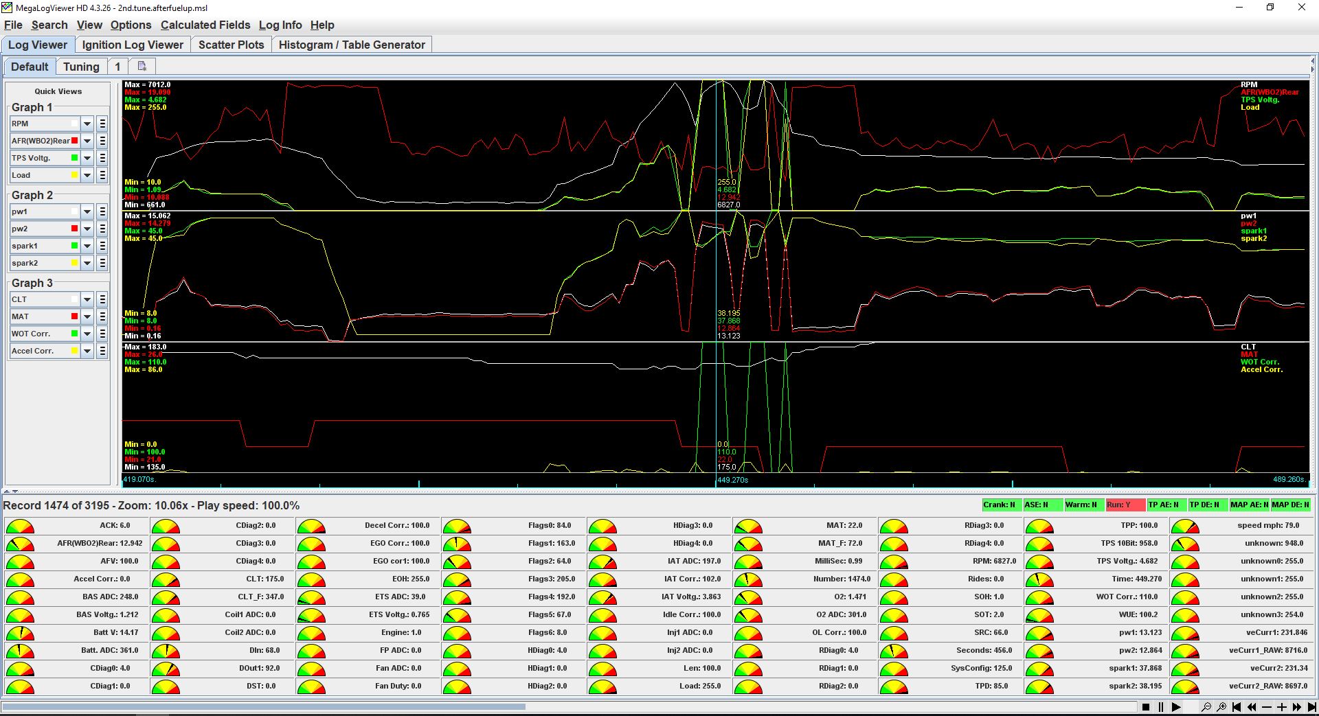
No, you need to disable closed loop to lock the ECM. Setting AFV to 100% simply takes out the AFV multiplier on all fueling cells when running the whole fuel map cells in open loop (doesn't apply to the other multipliers such as acceleration enrichment etc...). Again no global isn't correct on the AFV multiplier, only effects open loop. Closed loop changes in real time by the ECM when it is enabled by the NB feedback to closed loop cells targeting a constant 14.7 AFR. Look at megalog screen grab, on the right side there are 8 boxes just under the AFRbins box, see the fifth one listed ACCEL:Y in red? that is acceleration enrichment being applied in that moment of the datalog 13.7% additional fuel is being applied in that instance which you can see by looking at the third row on the first column in the "gauge icon" data. Also of note is this acceleration enrichment has sent my AFR to 11.38 even though my target AFR is 13.0 at this time stamp. Without acceleration enrichment being applied my AFR is almost perfectly 13.0 in this area of cells which you can see by tracing the AFR(WB02) white line back from the time stamp
Megalog Example 02voltang and AFR reading.jpg

The fuel map is wiped as it is not something anyone should be copying

Good infor on the 255 being the max injector duty cycle. I had hard time getting information around that topic. Also do you know what a PW is measured in MegalogViewer? For example, when at idle, PW for cylinders one and two are around 3. What does that 3 represent?
(PW) is pulse width, this is the measurement of the injector open (spraying fuel) in milliseconds (MS)during a cylinder intake cycle. It is much easier to look at the veCurr instead and divide by 255. So in the above screen grab that I time marked the veCurr is 227. 227 divided by 255 is 89% of the fueling capability (simplified) but easier to understand I think.

I'm still not quite sure on how you came up with the numbers to populate AFR in MegalogViewer using the scale https://graph.soft112.com. How did you get 7.3125 for 0v and 19.1875 for 5 v? Did you get/use data sheet for your WB sensor?

I'm using Bosch LSU 4.9 and hardware/driver from 14point7.com to make it run. I haven't looked at the data sheet for that controller to see exactly where the dead band is. Again, great find, but I'm lost as to how you came up with those numbers.

AEM AFR Chart.jpg
Here is the datasheet AEM supplies, you can see the last output for 8.5 AFR is .47 volts an on the other end 18.05 AFR is 4.52 volts after this voltage on either end it flat lines the AFR so not truly a linear line from 0-5 volts. This is why you use the graph program to make the linear line extending all the way from 0-5 volts then input that data into Megalog.
 
Also I do not know if 255 is actually 100% duty cycle on the injector, I would hope BUELL left a safety margin in them of 20% as it is well known not to tune past 80% duty cycle on an injector. All I know for sure is 255 is the most you can ask from them so I treat it as 100%.

If you get a datalog and happen to set a couple cells at 255 you can use this calculator I found to figure it all out. I'm kind of interested in the answer but not willing to datalog to find out any time soon.https://injector-rehab.com/shop/idc.html

EDIT:
Alright I ran the numbers from the previous post at the time stamp and got a duty cycle of 81.88% and not the 89% I quoted, so I ether messed up the math or there is a safety margin.
 
Last edited:
lowkey,

Where do you go in TunerPro to disable closed loop to lock the ECM? Also thank you for explaining this in good detail.

Well I came up with a little bit different numbers when calculating total injector open time percentage. Here is a link to my last post, https://www.buellxb.com/forum/showthread.php?55034-MLV-question/page3, page three, posts 21, 22 and 23 is where I finally got the information needed. Look it over and see if you agree.

Screen grab of of data log injector one PW=13.123. RPM 6827.

cx9ria5.jpg


At 6,827 rpm that is 58.89167 intake events per second and 0.017577 seconds between each individual intake event (17.577 mS between intake strokes). PW1 of 13.123mS / available amount of time 17.577 mS = 74.66 % injector spray time. Seems reasonable. Plus the AFR of 12.9 seems ok with the amount of fuel being burned.
Some one do the math make sure I'm not completely out in the weeds on this one. Now, again, I assume that PW1 and PW2 numbers are in mili seconds.


Ok it makes perfect sense how you came up with those voltage/afr numbers for you data. I need to find Bosch LSU 4.9 sensor data sheet and do the same.
Thanks lowkey, you are helping fill in some major gaps here buddy.
 
Last edited:
Also I do not know if 255 is actually 100% duty cycle on the injector, I would hope BUELL left a safety margin in them of 20% as it is well known not to tune past 80% duty cycle on an injector. All I know for sure is 255 is the most you can ask from them so I treat it as 100%.

If you get a datalog and happen to set a couple cells at 255 you can use this calculator I found to figure it all out. I'm kind of interested in the answer but not willing to datalog to find out any time soon.https://injector-rehab.com/shop/idc.html

EDIT:
Alright I ran the numbers from the previous post at the time stamp and got a duty cycle of 81.88% and not the 89% I quoted, so I ether messed up the math or there is a safety margin.

I cant get that web site to work. Founds this one https://www.stealth316.com/2-calc-idc.htm

Looks like my math above was correct. 6827 rpm and pw of 13.123 equals to 74.66% duty cycle.
 
lowkey,

Where do you go in TunerPro to disable closed loop to lock the ECM? Also thank you for explaining this in good detail.

I use ECMDroid to datalog. I will have to find how I was turning the O2 sensor on and off for the ECM to adjust off of. I just looked in ECMDroid but the option is grayed out. In old version of ECMSpy there is a check box to turn it off or on. I had a look through TunerProRT and cant find it. While I was digging for it I found a table for front cylinder correction which is interesting, looks like 2% is added at normal operating temperature and goes up from there. Probably a good idea to just make it 100% on fueling for all temps if you are datalogging and tuning the front cylinder (one less variable to overcome getting AFR's dialed in).

Ok it makes perfect sense how you came up with those voltage/afr numbers for you data. I need to find Bosch LSU 4.9 sensor data sheet and do the same.
Thanks lowkey, you are helping fill in some major gaps here buddy.

Not so much the sensor data but the controller data is what you need. Almost all WB's on the market use Bosch 4.2 - 4.9 or NGK sensor, it is how the controller reads the voltage in relation to AFR output that you want. Did you not get a datasheet to work off of?

I couldn't get the calculator on that link to work either but it has an example with the formula.

You can PM me your email and I'll email you my number if you want, it is much faster then on the forum.
 
Last edited:
Found it! I took my EEPROM and saved it with ECMSpy checked and unchecked for O2 off then loaded both into TunerproRT and had it check for differences in the EEPROM. Just need to put minimum RPM to enable O2 above the RPM limit of the bike so it never activates.:up:TunerProRT-turn off O2.jpg
 
Last edited:
Go to ECM parameters, error mask. There you will find a way to disable O2 sensor. https://www.buelltooth.com/open-loop.html

The error mask isn't turning off the O2 sensor just stops the flag from triggering the ECM. You can do the same procedure to turn off the O2 sensor in ECMDroid as the screen grab I posted above for TunerProRT. ECM Perameters>O2 setup>Minimum RPM>set above Motor RPM limit.
 
Be wary of the info on that site, I read through the link to the end you posted and there is bad info IMO... Read/save and reread/referance the ECMSpy MONO tuning guide, it will answer everything you come across! I linked it in this thread a couple pages back.
 
I use ECMDroid to datalog. I will have to find how I was turning the O2 sensor on and off for the ECM to adjust off of. I just looked in ECMDroid but the option is grayed out. In old version of ECMSpy there is a check box to turn it off or on. I had a look through TunerProRT and cant find it. While I was digging for it I found a table for front cylinder correction which is interesting, looks like 2% is added at normal operating temperature and goes up from there. Probably a good idea to just make it 100% on fueling for all temps if you are datalogging and tuning the front cylinder (one less variable to overcome getting AFR's dialed in).


Not so much the sensor data but the controller data is what you need. Almost all WB's on the market use Bosch 4.2 - 4.9 or NGK sensor, it is how the controller reads the voltage in relation to AFR output that you want. Did you not get a datasheet to work off of?

I couldn't get the calculator on that link to work either but it has an example with the formula.

You can PM me your email and I'll email you my number if you want, it is much faster then on the forum.

No never did get any data off of that controller or the sensor. Might have to contact 14point7 and see what they have to say.
How did you rig your WB?
Thanks for finding how to lock out the closed loop. Very clever lol, makes sense, just se the RPM way above bikes rev limit.

And I'm going to send you my email.

Be wary of the info on that site, I read through the link to the end you posted and there is bad info IMO... Read/save and reread/referance the ECMSpy MONO tuning guide, it will answer everything you come across! I linked it in this thread a couple pages back.

It has been my experience that the guy running it has very lackluster attitude towards a costumer that has difficulties with his product.
 
Last edited:
No never did get any data off of that controller or the sensor. Might have to contact 14point7 and see what they have to say.
How did you rig your WB?
Thanks for finding how to lock out the closed loop. Very clever lol, makes sense, just se the RPM way above bikes rev limit.

Hook up the sensor and pull it out of the header, what AFR and voltage reading do you get? If it reads max lean AFR and 0 volts you will need to track down the data if it reads max AFR but has a voltage percentage I think you could take that as the flat line point in the linear line, do the same in a propane rich cup with the sensor in it to find the voltage point on the other end of the AFR rich spectrum. I would contact for the chart to double check the data works exactly right though to be sure.

My setup is the gauge mounted to the handlebar as I posted then feed the bulk of the harness into the airbox and zip tie it to the filter cover then feed the wiring harness along the engine harness under the seat. The O2 sensor comes back out the airbox and gets zip tied to the clutch cable bracket on the right side near the front engine mount and into either the front or rear header pipe. The WB signal wire has good length and feeds from under the seat over the shock area into a cutout in the frame then plugs into the stock ECM harness plug for rear O2 sensor.

I can compare the enrichment tables of stock VS race EEPROM and take a screen shot.
 
Back
Top