
You are using an out of date browser. It may not display this or other websites correctly.
You should upgrade or use an alternative browser.
You should upgrade or use an alternative browser.
ecmspy wireless schmatic
- Thread starter wutend007
- Start date
Help Support Buellxb Forum:
HammerBuell
Well-known member
- Joined
- Sep 5, 2012
- Messages
- 102
Link worked for me. Good info on there.
As far as I understand it as long as your using a chip designed to work at ttl voltage level (5v) then all you have to worry about is the power supply voltage from the ecm with a voltage regulator. The link suggest using IC 78L05.
As far as I understand it as long as your using a chip designed to work at ttl voltage level (5v) then all you have to worry about is the power supply voltage from the ecm with a voltage regulator. The link suggest using IC 78L05.
chief_of_smoke
Well-known member
im with wutend007. i need to see the back of the board to see where the conection are made. i can made a board look like the pics, but with out knowing which lead conect to where i cant make it work. even reading it with what pic are given doesnt help. i need to see the solder points and conections.
HammerBuell
Well-known member
- Joined
- Sep 5, 2012
- Messages
- 102
i'm just waiting for my connector to arrive and I will post a diy when I'm done.
But if you can't wait:
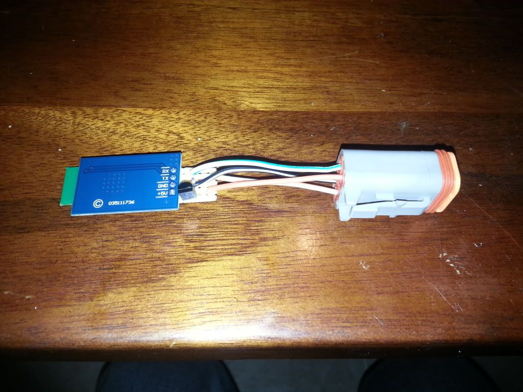
Red goes to the voltage regulater, then from the voltage regulator to the power input on the BT Module.
Blue goes to Ground
Brown goes to Tx (Transmit Data)
Yellow goes to Rx (Receive Data)
If you are unsure how to connect the voltage regulator see the data sheet HERE
On the example on the ECMSpy link above, the red jumper wire across the board is used to connect the CTS (clear to send) and RTS (request to send) together. These connections are for flow control, which would be used in a network environment to reduce packet loss and data collisions from multiple computers or devices sending data to the same access point at the same time. The bare basics of how this works is device A on the network wants to send data, so it send a request over the RTS line and waits for a response on the CTS from the access point. So essentially device A is waiting for its turn in line to send its data. By jumping these connections the device is clearing itself to send data (the request sent on RTS is immediately received on the CTS)
Not all BT Modules have these extra ports for CTS and RTS (the one I'm using does not) and yours may have something different like a state or status output. It all depends on the module you have, but all will have the basic 4 connections of power, ground, Rx, Tx.
But if you can't wait:
Red goes to the voltage regulater, then from the voltage regulator to the power input on the BT Module.
Blue goes to Ground
Brown goes to Tx (Transmit Data)
Yellow goes to Rx (Receive Data)
If you are unsure how to connect the voltage regulator see the data sheet HERE
On the example on the ECMSpy link above, the red jumper wire across the board is used to connect the CTS (clear to send) and RTS (request to send) together. These connections are for flow control, which would be used in a network environment to reduce packet loss and data collisions from multiple computers or devices sending data to the same access point at the same time. The bare basics of how this works is device A on the network wants to send data, so it send a request over the RTS line and waits for a response on the CTS from the access point. So essentially device A is waiting for its turn in line to send its data. By jumping these connections the device is clearing itself to send data (the request sent on RTS is immediately received on the CTS)
Not all BT Modules have these extra ports for CTS and RTS (the one I'm using does not) and yours may have something different like a state or status output. It all depends on the module you have, but all will have the basic 4 connections of power, ground, Rx, Tx.
Josh662234
Well-known member
- Joined
- Dec 22, 2011
- Messages
- 358
Hammer, did you finish yours yet? Which modem did you use?
HammerBuell
Well-known member
- Joined
- Sep 5, 2012
- Messages
- 102
No still waiting on a connector
Should be in this week, I hope. Once its in I will put together a diy.
The chip is from MDFLY, can be found on ebay, and was around $15. Its supposed to operate at 5v on the data lines not 3.3v like most of the cheaper modules, meaning I should only have to regulate the B+ input down to 5v. We'll see.
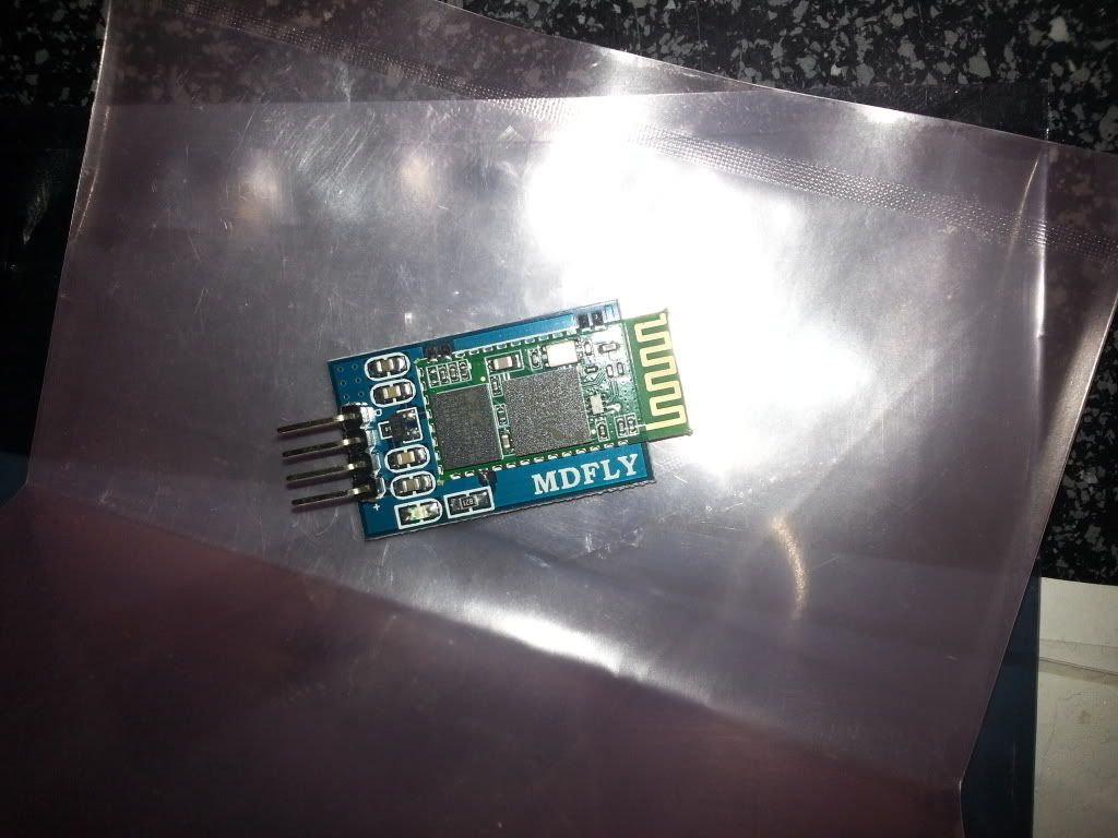
chief_of_smoke
Well-known member
i ordered 2 different blue tooth chips. the blesmirf willbbe here this week and the other will be here next month. the other coponets will be here this week as well. i now understand all the connections on the backside of the board. had to look at a ciruitboard to understand how they did it. it really is basic wirering and soldering. hopfully ill have one built by the end of the week. also im building a usb cable as well, which will be done by the end of the week. i got my chips and plugs from amazon. the voltage regulator form digikey. ill post pics and write up if hammer doesnt do it first.
HammerBuell
Well-known member
- Joined
- Sep 5, 2012
- Messages
- 102
Sounds good chief, even if I do you should write yours as well since we're using different chips.. the more information out there for everyone the better ")
chief_of_smoke
Well-known member
ok will do.
HammerBuell
Well-known member
- Joined
- Sep 5, 2012
- Messages
- 102
Ok so a little update on my DIY.
Put everything together, connected to the bike and all was well.... for about five minutes, then started getting intermittent communication issues, then lost the connection and never got it back. Right away I knew the issue, the Tx/Rx lines of the module (specifically the Rx) must have been overloaded by the 5v on the ecm's data lines.
I messaged the fine people at MDFly, through Ebay, told them how I bought their module because it specified 5v operation, and asked them what the operating voltage on the Rx/Tx lines should be, to which they replied
"3.3v, though they work on 5v MCU's (most) your ECM's 5v must have been too much. We will send you another, please step down your Rx/Tx to 3.3v" Really good of them to do that tbh
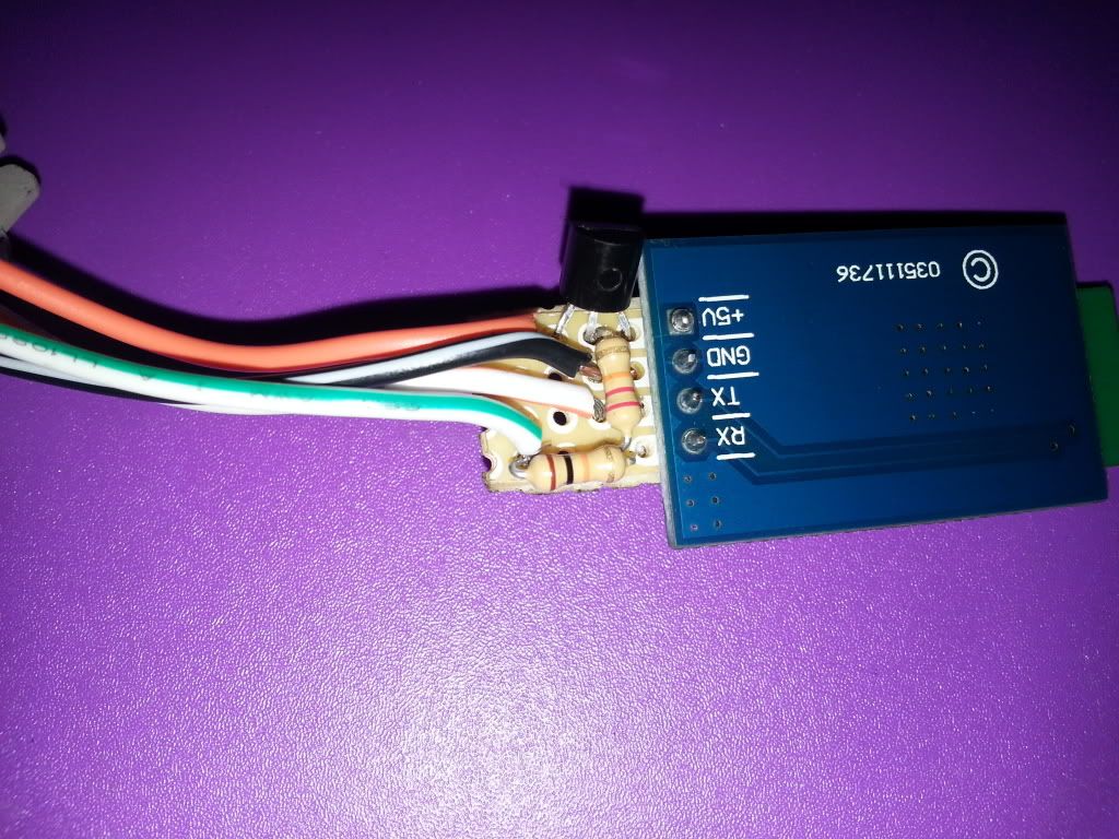
So I decided to add a resistor voltage divider circuit to what I had already built and just make sure it stepped down to the 3.3v required while I wait for the new module,
As it stands I am going to wait until I have it working well for a week or 2 before I post the DIY. It sucks that the module was not actually 5v on the data lines as they advertised, but that is the norm on all these cheap Ebay so I should have known, but I really wanted to keep it as simple as possible.
Unfortunately the Rx for sure will have to be stepped down with a resistor voltage divider circuit which in itself is not that complicated, it just adds 2 more parts and more soldering and planning for your board. The good news is the DIY will now be for 3.3v modules which should allow you to buy any of the cheap Ebay options.
I put together a quick little diagram for those who are interested
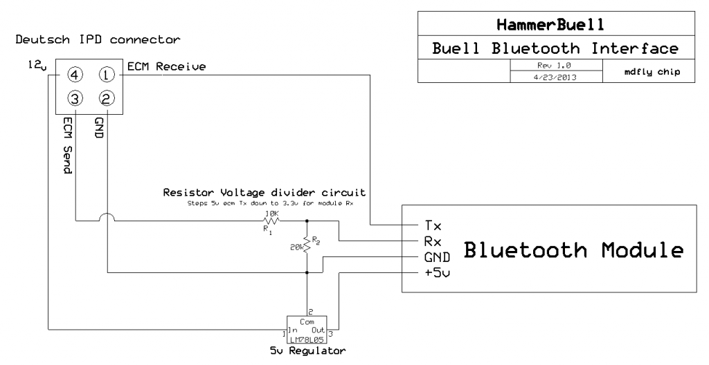
A few notes on that diagram, first if your module specifies 3.3v supply voltage you will NEED a 3.3v voltage regulator. Second, position of the 10k and 20k resistor's does matter, don't get them backwards or the voltage will not step down as intended.
Put everything together, connected to the bike and all was well.... for about five minutes, then started getting intermittent communication issues, then lost the connection and never got it back. Right away I knew the issue, the Tx/Rx lines of the module (specifically the Rx) must have been overloaded by the 5v on the ecm's data lines.
I messaged the fine people at MDFly, through Ebay, told them how I bought their module because it specified 5v operation, and asked them what the operating voltage on the Rx/Tx lines should be, to which they replied
"3.3v, though they work on 5v MCU's (most) your ECM's 5v must have been too much. We will send you another, please step down your Rx/Tx to 3.3v" Really good of them to do that tbh
So I decided to add a resistor voltage divider circuit to what I had already built and just make sure it stepped down to the 3.3v required while I wait for the new module,
As it stands I am going to wait until I have it working well for a week or 2 before I post the DIY. It sucks that the module was not actually 5v on the data lines as they advertised, but that is the norm on all these cheap Ebay so I should have known, but I really wanted to keep it as simple as possible.
Unfortunately the Rx for sure will have to be stepped down with a resistor voltage divider circuit which in itself is not that complicated, it just adds 2 more parts and more soldering and planning for your board. The good news is the DIY will now be for 3.3v modules which should allow you to buy any of the cheap Ebay options.
I put together a quick little diagram for those who are interested
A few notes on that diagram, first if your module specifies 3.3v supply voltage you will NEED a 3.3v voltage regulator. Second, position of the 10k and 20k resistor's does matter, don't get them backwards or the voltage will not step down as intended.
Here is the older how-to
http://www.buellxb.com/Buell-XB-For...s/How-To-Build-your-own-Wireless-ECMSpy-cable
http://www.buellxb.com/Buell-XB-For...s/How-To-Build-your-own-Wireless-ECMSpy-cable
chief_of_smoke
Well-known member
i have read the thread. like to see the pictures tivolya had up. so in my guess to mation, the bluesmirf chip aslo had to be stepped down?
HammerBuell
Well-known member
- Joined
- Sep 5, 2012
- Messages
- 102
Just the 12v supply, which they did with a 5v regulator. I believe the bluesmurf is 5v regulated on the board itself for the data lines.
Loki.. what I'm trying to achieve is a dirt cheap alternative. Total in parts I'm under $35, and once built, if the module gets wet or whatever, $10 and 2 weeks ans you'll be up and running again.
Loki.. what I'm trying to achieve is a dirt cheap alternative. Total in parts I'm under $35, and once built, if the module gets wet or whatever, $10 and 2 weeks ans you'll be up and running again.
chief_of_smoke
Well-known member
i like your conceot hammer
chief_of_smoke
Well-known member
i like your conceot hammer
Blaylock1988
Well-known member
- Joined
- May 27, 2011
- Messages
- 314
I think that board's input rating was overstated. the TX and RX pins on my arduino are rated for 5V and i had 0 problems for the 20+ hours i have had that thing plugged into my bike.
HammerBuell
Well-known member
- Joined
- Sep 5, 2012
- Messages
- 102
Yeah for sure. They are sending me another for free but asking that I step the data lines down to 3.3v.
But in the same sentence telling me I should be fine for 5v... hrrmm
But in the same sentence telling me I should be fine for 5v... hrrmm
Blaylock1988
Well-known member
- Joined
- May 27, 2011
- Messages
- 314
Hopefully stepping it down won't affect the data stream quality too much.
Similar threads
- Replies
- 11
- Views
- 569
- Replies
- 4
- Views
- 12K
- Replies
- 3
- Views
- 246