• You are currently viewing our boards as a guest which gives you limited access to view most discussions and access our other features. By joining our free community you will see less advertisements, have access to post topics, communicate privately with other members (PM), respond to polls, upload content and access many other special features. Registration is fast, simple and absolutely free so please, join our community today!

    If you have any problems with the registration process or your account login, please contact us.

How-To: Crank Case Breather Mod (with pics)

Buellxb Forum

Help Support Buellxb Forum:

Urban_Assault

Well-known member
Joined
Dec 14, 2008
Messages
223
I've been reading a lot on the Crankcase Breather Mod, but had to dig around to find out how to do one.

I know there's another thread on this forum, that's what I used to get started on mine. I'm just updating the parts list, and adding pictures.

It's a pretty simple mod, so here's a step-by-step that should help you along.

Here's what you'll need:

(5ft) - 3/8" I.D. Transmission Oil Cooler hose, cut to the following sizes:
- 10" piece
- 2" piece
- 24" piece
- 18" piece
- 6" piece

(1) - Breather Filter with 3/8" connector
(2) - 3/8" Vaccuum T's
(4) - 3/8" hose clamps
(1) - Radiator Drain Cock with 3/8" threads
(4-6) - Zip Ties
(12") - Electrical Tape

Scroll down for directions.


IMG_3531.JPG

IMG_3532.JPG

IMG_3533.JPG

IMG_3534.JPG

IMG_3535.JPG

IMG_3536.JPG
 
Step 1:

Remove your seat and airbox cover

Disconnect the vent hose from next to the Fuel filler cap, then remove the airbox lid.

Disconnect the two vaccuum lines and the sensor wire from the bottom of the airbox base, then remove the airbox base.

IMG_3537.JPG

IMG_3538.JPG

IMG_3539.JPG

IMG_3540.JPG

IMG_3542.JPG

IMG_3543.JPG
 
Step 2:

Remove the two factory vaccuum hoses.
Remove the braided nylon sheath from the longer hose.

Connect the new 10" and 2" hoses with a vaccuum T.

Place the nylon sheath over the 10" hose.

The sheath is actually a little longer than the hose, but if you work it down it will fatten up and get shorter.

Wrap a few loops of electrical tape around the edges to hold them in place and keep it from fraying.

IMG_3554.JPG

IMG_3555.JPG
 
Step 3:

Run the 24" hose down the front of the motor, past the oil cooler bracket, then back along the frame support rail.

Connect the 24" hose to the 2"/10" vaccuum T, with the 2" hose towards the front and the 10" hose towards the rear.

Connect the 2"/10" breather hoses to the crankcase breather ports.

IMG_3557.JPG

IMG_3558.JPG

IMG_3561.JPG

IMG_3560.JPG

IMG_3566.JPG

IMG_3563.JPG
 
Step 4:

Connect the Radiator Drain Cock to the 18" hose.

Run the 18" hose up the back of the crankcase, then along the frame support rail.

Connect the 18" hose to the 24" hose using another 3/8" vaccuum T.

Conncet the Breather Filter to the third port on the vaccuum T.

Zip-tie the 18" and 24" hoses along the frame support rail near the filter. This should hold everything in place.

IMG_3569.JPG

IMG_3571.JPG

IMG_3572.JPG

IMG_3570.JPG
 
Step 5:

Stuff one end of the 6" hose into the vent hole on the bottom of the airbox base.

Loop the other end over and stuff it into the second vent hole. The will seal off the airbox and make sure dirty air doesn't get past the filter.

Put everything back together, then go for a ride!

It will probably run like crap for a while until the computer can re-calibrate itself. It should smooth out after about 15-20 miles of mixed city/highway driving.

Good luck!

-Tim

IMG_3574.JPG

IMG_3575.JPG

IMG_3576.JPG

IMG_3540.JPG

IMG_3538.JPG

IMG_3537.JPG
 
First off great write up.[up][up]

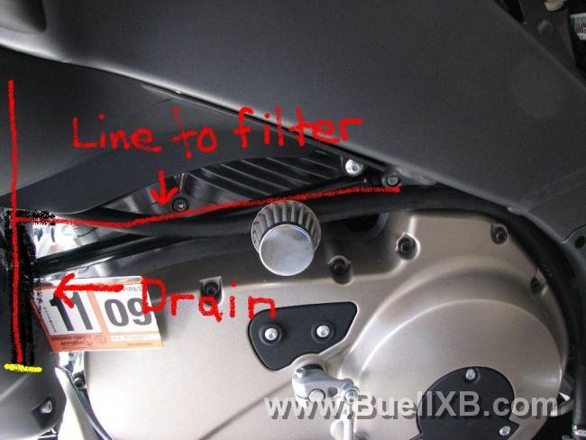
But just so you know the drain or petcok should go before the breather otherwise it will all blow out of the filter instead of going to the drain.[up][up];)
 
I am about to do this mod, and i'm curious as to what you mean fastxb12r? Instead of having the filter in-line, you should run a line down before it and then a line to the filter?
 
See my edited illustration below for a better understanding. The drain should be in the front to catch all the head gases and oily residue. Then the filter should be ran off of the tee.

2792_20081216070523_L.jpg


[up][up]
 
I was actually just getting ready to reply. It doesn't look like it in the picture, but the hose is actually angled down as it goes back.

Due to the viscousity properties of the oil, it will tend to stick to the inner walls of the tube. As long as it is angled this way, it will flow towards the drain.

hoses.jpg


The filter will block any large drops of oil from blowing out the vent, so you don't have to worry about spitting oil all over the side of your bike. The drops will again drain down the tube towards the valve.

The internal volume of that last 18" piece of tube is just shy of 8 cubic inches, which is a little over 1/8th of a quart. Plenty to act as a catch can.

There are several different ways of routing the hoses, I just wanted something simple that didn't look too bulky. So far, I haven't had any problems with it.

It would be easy to mod this setup to match Buell_Cru's illustration. Just add a 3rd vaccuum T where the hose loops next to the air scoop. Run one line straight down, and the other towards the back.

Good luck!
 
I understand the details as far as adding grade to your line so that it will still drain in a downward motion but that wasn't explained for the guys with not as much mechanical knowledge.

Good mod.

[up][up]
 
I understand the details as far as adding grade to your line so that it will still drain in a downward motion but that wasn't explained for the guys with not as much mechanical knowledge.

Good mod.

[up][up]
 
Totally understood. In all honesty, if I had seen your post I would have done it that way. Less chance of clogging the filter from the inside.

In fact, I'll probably modify it this week to run the drain straight down. I'll post another pic when it's done.

Thanks for the heads-up.

-Tim
 
great Write up. I agree that the filter should be up from the drain but you could leave it in the same location just rotate it up so the oil flows under the filter.
 
I'm wondering now if there's a way to put a couple of schrader-valves on this setup.

One near the filter, to only allow fresh air in

The other near the drain, to only allow oil/dirty air out.

It would basically make a one-way downdraft airflow circuit. Would eliminate the need to drain the valve, still allow the system to breathe, and not allow debris back in.

Maybe I'll pick up a couple of schrader valves today and see if I can fit them inside the tube.

Any thoughts?

hoses2.jpg
 
Used a single 3/8 nylon T and 3' of gas hose from Napa Auto. Used one of the "old" pieces of tubing to plug the cover holes-similar (a U) to what is shown in the pic. Nothing on the end..just terminated it at the muffler outlet. Havent seen anything drip from it yet and if it does, the exhaust pulse will simply blow it outwards away from any possible contact with the tire. Easy job-took maybe 1/2 hr and it does seem to idle smoother.
 
great pics. the problem with running it the way the pics are that all the crap will build up in filter and drip on cases
 
Seriously...unless you live in Cali, then dont even worry about the valve at the end......gotta leave your mark somehow....:D
 
Back
Top