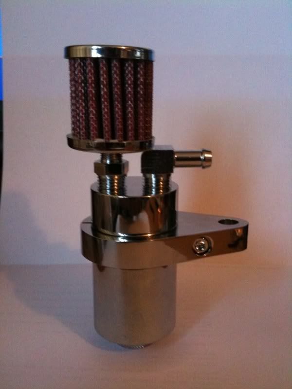
Okay. I've read this whole thread, and a lot of it twice. I believe that it helps the way the engine runs; why it works isn't that important. But, I have a question as to how the filter is being set up:
First, tell me if I misunderstand the basic layout: I gather that there's a vent/breather line from each cylinder that vents crankcase gases to the airbox. The modification is to route these out of the airbox, correct? In the diagram, I show a hose from each cylinder, connected at "Tee 1". Another hose runs from that Tee to Tee 2, where the filter is attached. The purpose of the filter is to prevent debris from being able to go back upstream and into the engine. From the remaining branch of the tee, a hose is either routed to drain/vent, or is put into a catch can.
Correct me if I've got this wrong.
Here's where it appears to me that it goes off the rails. At "Tee 2," there should be no difference in the supposed vacuum on either side of the tee. In fact, there should be more resistance to vacuum through the filter than through the open end. So, unless there's a check valve downstream of the filter (at point "X") that prevents air from being drawn in from that direction, there's no reason that the filter does anything at all. It might get dirty, since at that point in the system, outflow pressure is equal, and the oily gases will get pushed through from the inside, but it seems that not much is going to get drawn through from the outside. To close the system and make the filter functional, it seems that you need to cap the "drain" line.
If I've completely missed the bus, please let me know.


