• You are currently viewing our boards as a guest which gives you limited access to view most discussions and access our other features. By joining our free community you will see less advertisements, have access to post topics, communicate privately with other members (PM), respond to polls, upload content and access many other special features. Registration is fast, simple and absolutely free so please, join our community today!

    If you have any problems with the registration process or your account login, please contact us.

Wiring Guru NEEDED

Buellxb Forum

Help Support Buellxb Forum:

flaya564

Well-known member
Joined
Apr 13, 2009
Messages
1,346
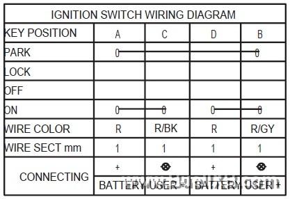
So I had to buy a new ignition. I was able to pick up a Motogadget M-Lock for little over 150. What I was hoping to do was to use the existing connector from the the ignition and wire the m-lock to it. Since my old ignition is broken I can't do any tests to see which wire does what. What I do know is that both red wires are hot and the red and grey wire is for the parking light.

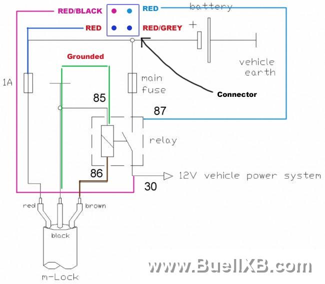
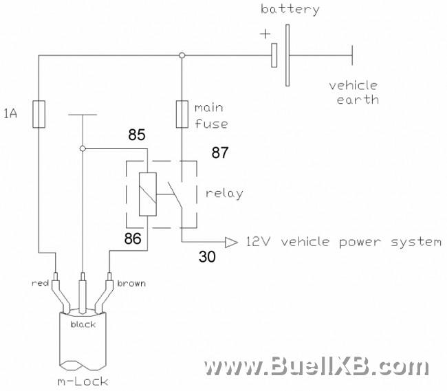
I've attaching the diagrams for the M-Lock, the wiring diagram and the connector I cut of the ignition.

GET TO WORK lol. Seriously though, please help if you can.
3555_20120313125504_L.jpg

3555_20120313125431_L.jpg

Top left is the red/black, top right and bottom left are the red wires, and I took out the red grey wire
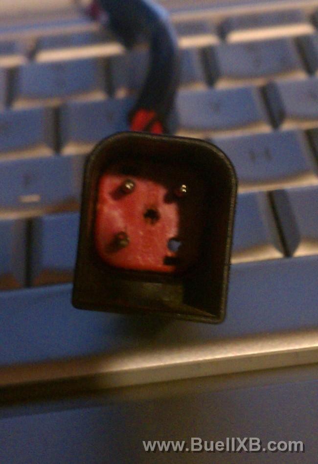
3555_20120313125159_L.jpg
 
bike -> mlock
2red(or just pick one they are the same wire) ->red
ground ->black
red/grey & red/black -> brown

you still need the red/grey im pretty sure.

looking at the table for the ignition switch when the key is in the on position is closes the circuit between red and red/grey and the other red and red/black.

when the key is in acc it only closes red with red/grey. the m lock doesnt seem to have the acc feature.

4834_20120313160512_L.jpg
 
In this scenario, it would appear that I wouldn't use the supplied relay , correct?.

On the hand, if I attempt the diagram as is, I get a little lost where the relay comes in. RELAY: brown to relay position 86, a separate ground to position 85, position 87 and 30, I'm unsure of.

And does all that bypass the stock ignition?

Too expensive to screw up.
 
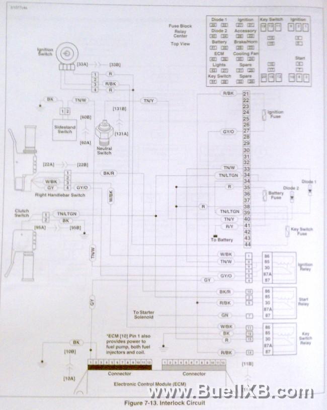
Yea you don't need the relay. The red/grey and the red/black wires already go to relays.
 
Thanks a bunch Kona! I just need a confirmation on this and I'll be ready to start. Nothing against what you've said , it would be an expensive mistake if i do it wrong.

It makes sense to me.
 
Fwiw I am an engineer. And while I was in grad school I installed engines on dynos and fully instrumented them. I've done lots of wiring with data aqs, ecu harnesses, and pid controls. I understand you wanting an extra blessing though. Be sure to update this and let us know how it went.
 
my bad. looking at the traces closer they power some things outside of the relay so you will need the relay that came with it. i hate it when that happens but thats what they make fuses for.

i would wire 1 red from the bike to the m lock red with a 1A fuse like it shows. then wire the other red to the #87 pin. the "main" fuse will have to be able to handle the acc and brake/horn/muffler circuit together which is 7.5A + 15A. So a 25A fuse would seem to be appropriate here. The individual circuits will still be protected by the smaller fuses. One thing to check would be the size of the red wire on the bike. I see how its laid out on the schematic but im not sure exactly how on the bike. It should be 12ga wire or bigger. 14 ga would probably work too but its on the edge.

wire the black wire from m lock to 85 on relay and ground of bike.

brown to 86.

then 30 to red/blk and red/gy

i feel dumb because i originally had this thought about the relay last night but convinced myself that they powered relays which they do but they also power the acc circuit and lights circuit without a relay. (that would be the post i edited to say nevermind)
 
Before I realized the fuse was blown that's exactly how I set it up. which fuse am I swapping out with the 25a?
 
you blew the 1A fuse using the relay? that should not be happening. the only load on the 1A fuse should come from the m lock device and the relay

is there a fuse that connect to 87 on the relay like shown on the diagram. what size is that one?

that red wire is fused at 15A anyway with the key switch fuse so you really dont need one at the relay again. It is strange because that then goes on to power the brake/horn/muffler which is also a 15A fuse and the acc circuit which is a 7.5A fuse. the brake/horn/muff and acc fuses must be over sized if they both are supplied by a 15A circuit. i just threw that 25 out there because it theoretically should be able to supply both of those circuits at full load but that must not be the case.
 
I don't know if the fuse was blown before hand, I never heard a pop or anything. So I'm going to get a bunch of fuses and try everything again.
3555_20120315010622_L.jpg
 
SHE'S ALIVE!!!
Just replaced the 1AMP fuse and wala!

Thank you so much Kona for your help. I couldn't have done it without you.

Now to solder and heat shrink everything together.
 
Awesome! I want one now.

copy the characters between the = and the & if there is one. "tgjIEcUGeJk"

 
Back
Top